Simple Schematics
Drawing & documentation for AV

Simple Schematics

Draw the system once. The cable schedule, the rack elevations, the screen build and the projection study all come out of the same drawing — instead of being typed out again beside it.

An account is needed to use the app. Everything below is what it does before you sign in.
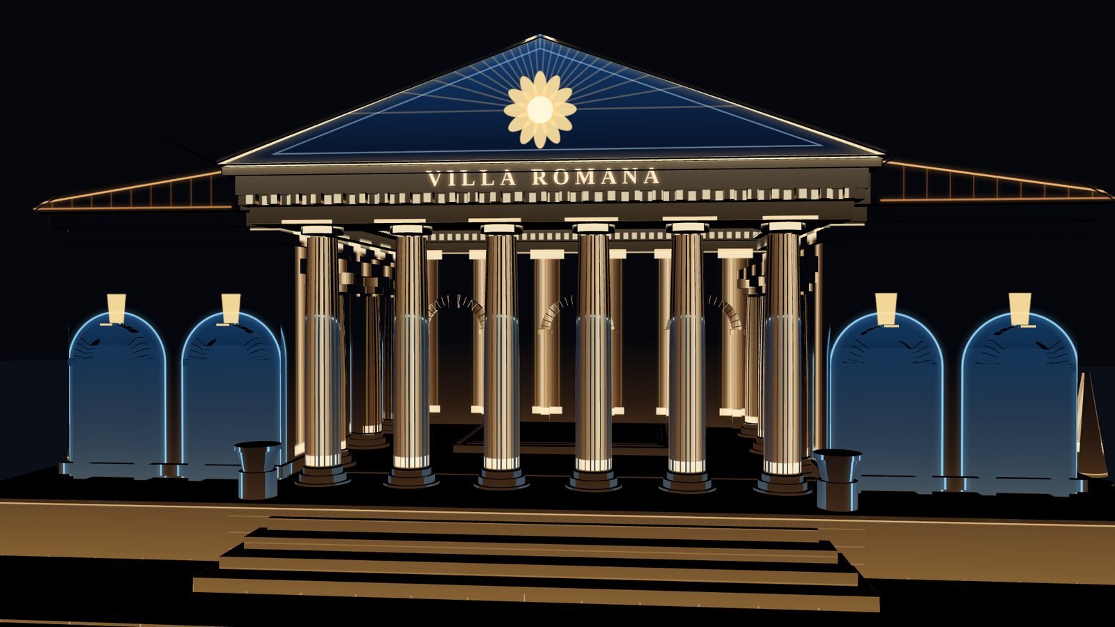
A Roman villa facade at night with projection mapped onto it: lit columns, glowing arcade arches and a pediment rosette
See the show before anything is rigged. Content mapped onto a 30 × 25 m courtyard villa — every column, arch and the pediment taking its own part of the picture. Modelled and rendered in the app from the imported OBJ.

What it does

Six things, all reading from one drawing, so the paperwork and the picture can never disagree.

Signal flow schematics

Devices from a library of real equipment, cabled together. Connectors, card slots and signal types are the manufacturer's, not generic boxes.

Cable schedules

The schedule is the drawing. Every cable is numbered, typed and listed as you draw it, and exports as CSV or into the printed pack.

Racks

Rack elevations with rack units, weights and the kit list that follows from them — built from the kit already on the drawing.

LED screens

Build a screen from the cabinets you actually have. Data runs, sending cards, power circuits and Socapex feeds are worked out and drawn.

Projection

Throw distances, lens choices from the manufacturers' own ranges, blends, lux on the surface — flat, pitch, dome and full 360°.

Outputs & test patterns

Plan what each physical output carries, then send it to a second screen — a test pattern at native pixels, or the room seen from a saved camera.
From artwork to building

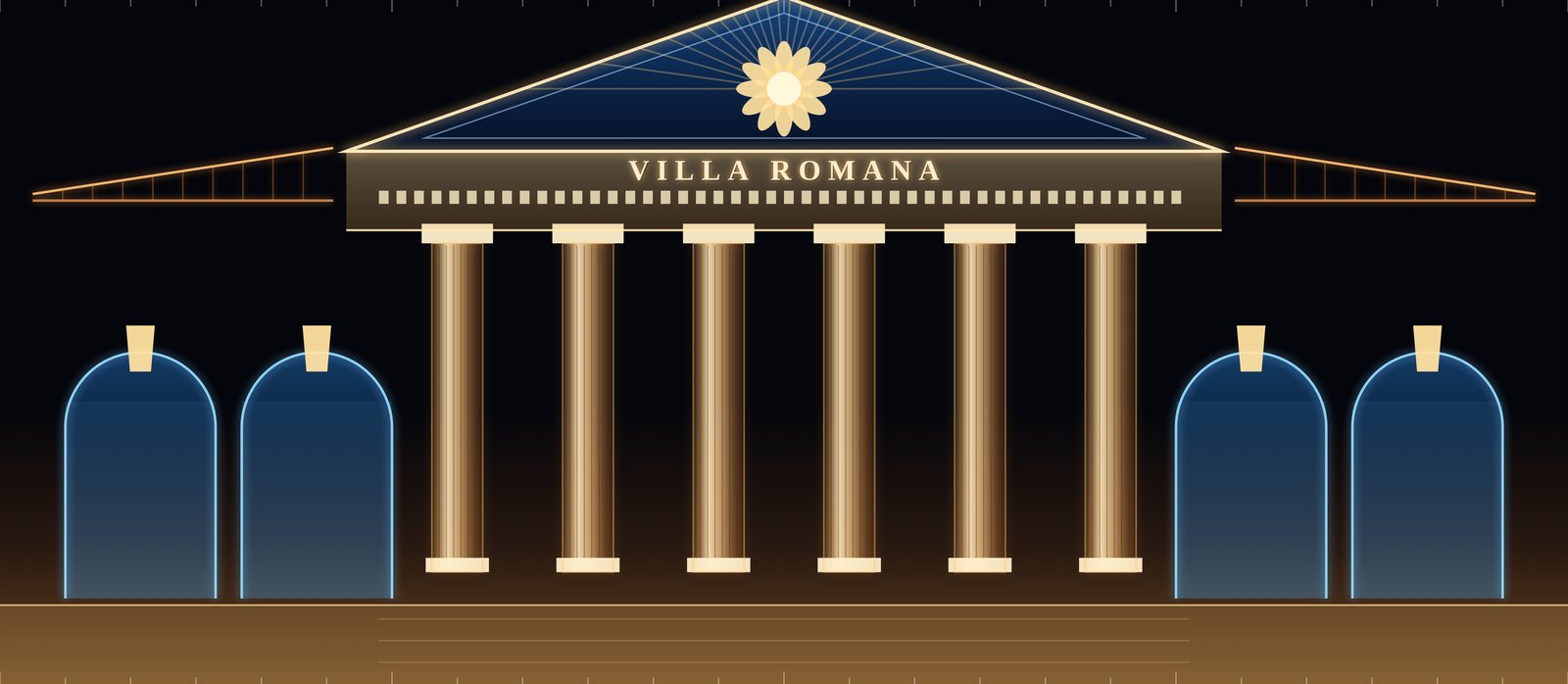
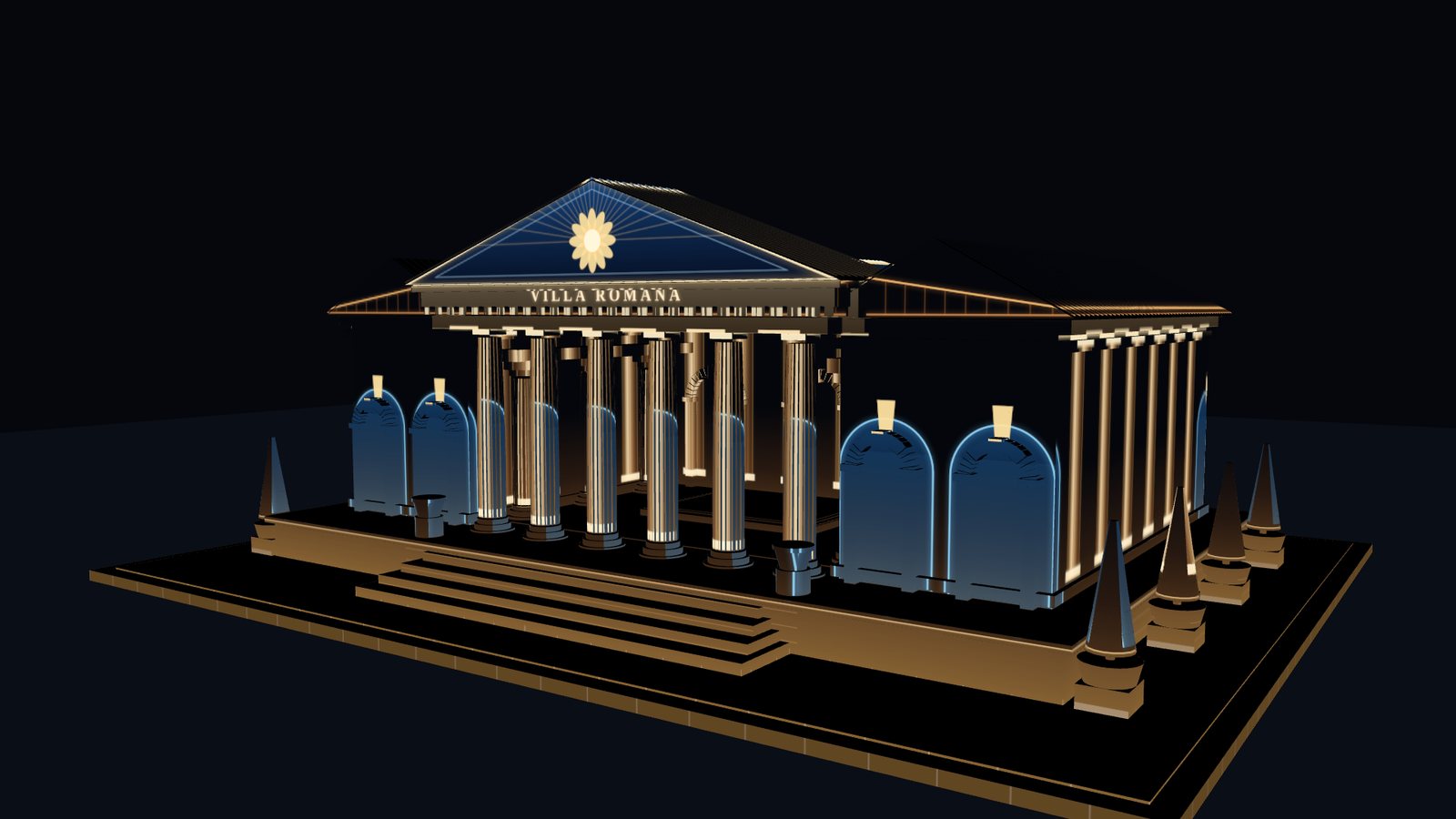
Content is authored against the elevation, then mapped onto the real geometry — so a stripe meant for a column lands on that column and wraps it, instead of being flattened onto a screen in front of the building. The roof takes no light at all.

The content artwork: a facade elevation with lit columns, glowing arches, a dentil frieze and a pediment rosette on black
The artwork, authored to the facade. Column centres, arch springs and the pediment are taken from the model, not estimated.
The same artwork mapped onto the villa in three quarter view, the tiled roofs left dark
The same artwork on the building. Forty projectors on four elevations; the tiled roofs are never in a beam.

Projection, worked out properly

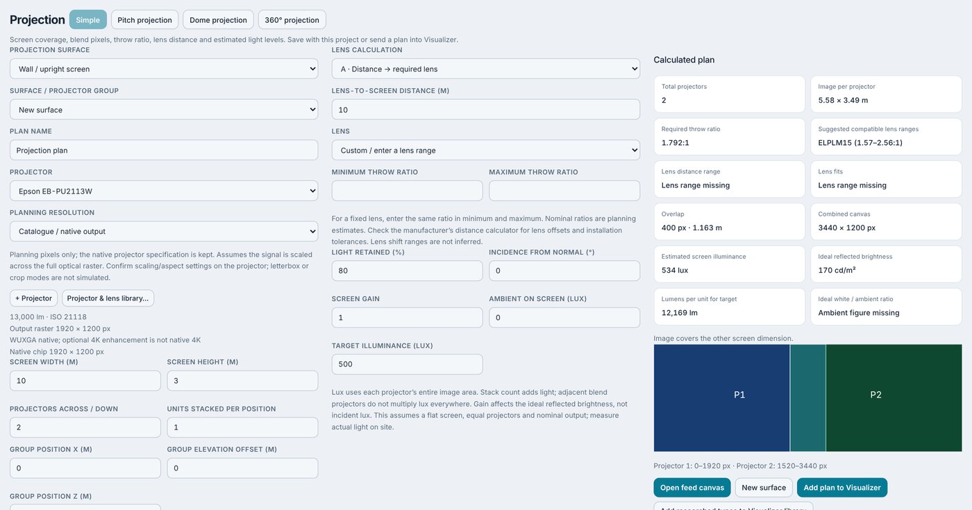
Pick the projector and the lens from the real catalogue, give it the surface, and it tells you the throw ratio, the blend overlap in pixels and in metres, the canvas you have to author to, and how much light actually lands.

12projectors, 4 × 3
14160 × 6400canvas pixels
574 luxon the facade
72.8 : 1white to ambient
The projection calculator showing a twelve-projector grid study for a 24 metre facade
A 24 × 10.6 m facade covered by twelve 4K projectors at 26 m, with the suggested lens range and the blend overlap.

Screens that cable themselves

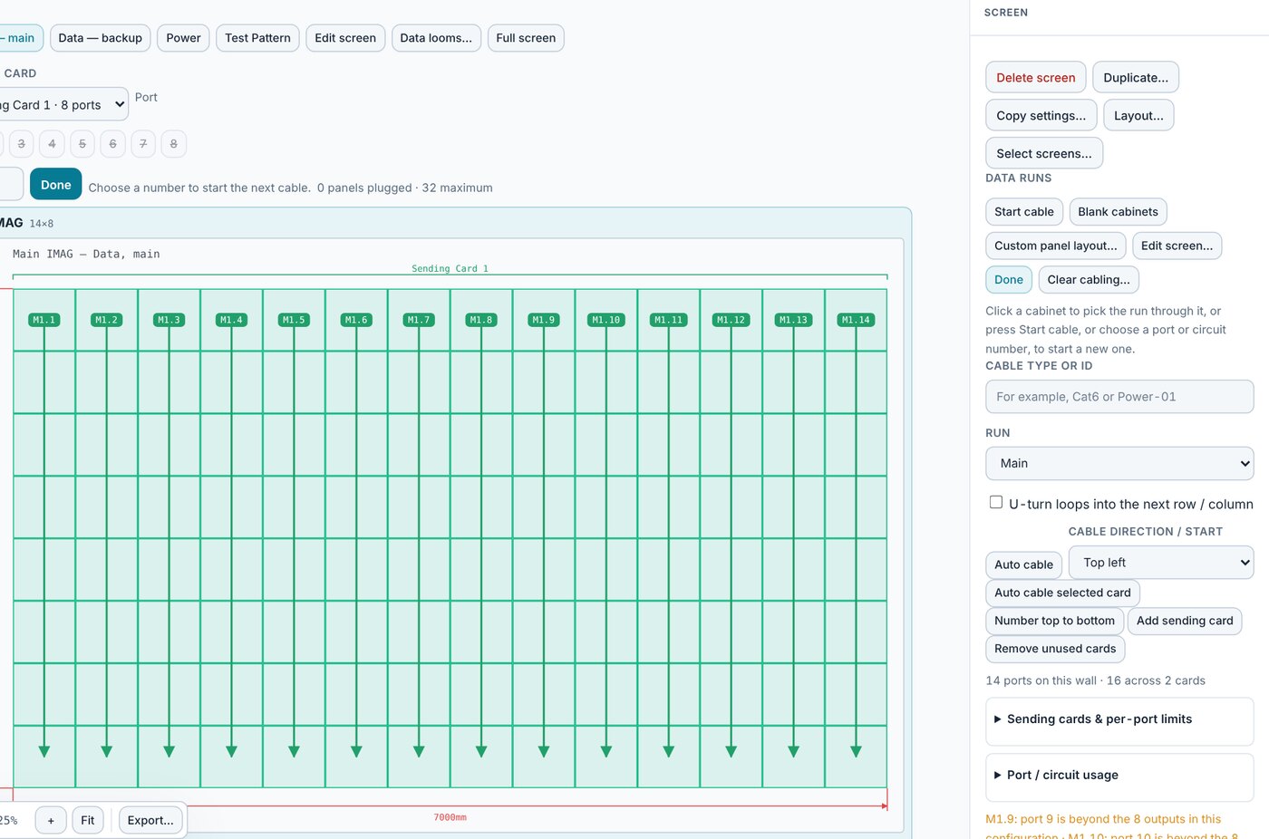
Choose the cabinet and the processor and the wall is worked out from them: pixel count, weight, power, and how many sending cards it really needs. Auto-cable the data runs, and when the ports do not add up it says so and offers the cards to fix it.

14 × 8cabinets
7.0 × 4.0 mfinished wall
1.8 Mpxat native pitch
An LED screen of fourteen by eight cabinets with its data runs drawn and numbered
Fourteen data runs across a 14 × 8 wall, numbered in the order they are patched.

Test patterns with your name on them

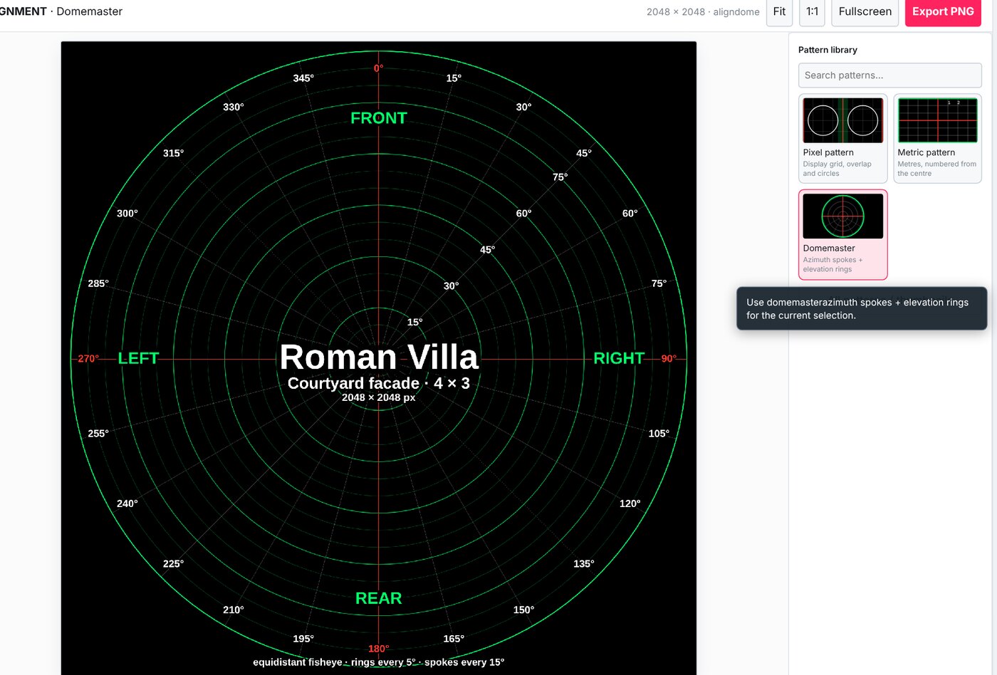
Cabinet maps, colour bars, focus targets, crosshatch, metric grids and equidistant domemasters — at the exact pixel size of the wall or the feed. Put the project and surface name on them, drop in as many logos as you like, and export the file you will actually send.

A domemaster alignment pattern with azimuth spokes, elevation rings and the project name printed on it
An equidistant fisheye reference, named for the job it belongs to.

Bring the room in

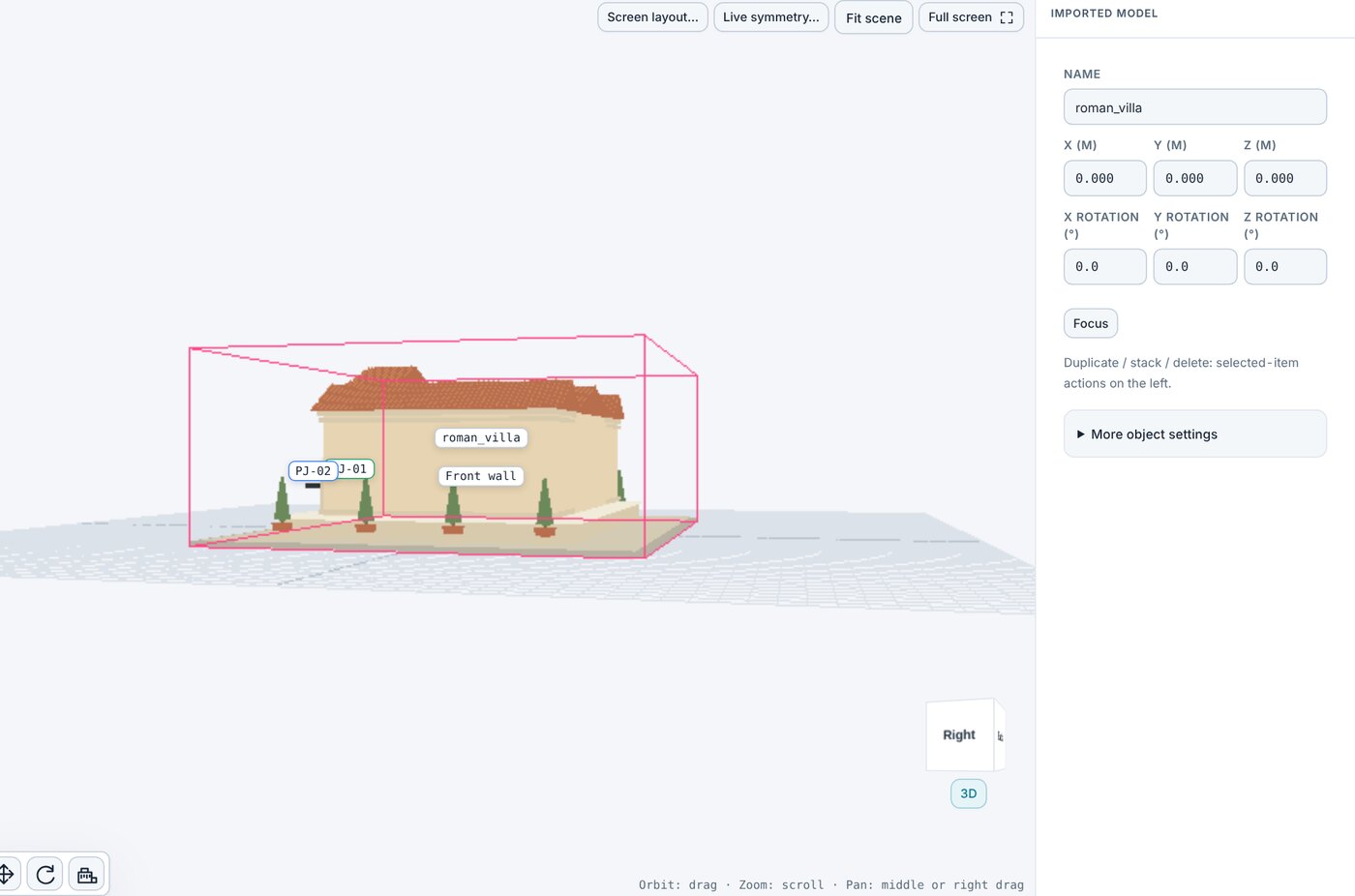
Import an OBJ, STL, GLB or glTF of the venue or the set, in its own colours, and place projectors against the real thing. Walk through it from any seat, save the viewpoints, and print them into the pack.

The same villa model seen from another angle in the 3D visualiser
Any angle, any seat. Cameras you add are printed in the PDF, and two or more play as a walk-through.

What it does with your data

Drawings are saved in your own browser on the device you drew them on, and export as PDF, SVG, Excel, CSV or a project file. You can also connect your own Google Drive or Dropbox, and project versions are then written straight from your browser to your account — we keep no copy. That connection is optional, off until you turn it on, and limited to the files the app itself creates. The privacy policy sets out exactly what is stored and where.

Planning aid, not an engineer. The calculations are estimates from the figures entered into them. A competent person must check any design before it is built, hung, powered or rigged.

Who it is for

Technicians, project managers and system designers working on live events, installs, broadcast and staging — anyone who has drawn a signal flow in a general-purpose drawing package and then typed the cable schedule out again by hand.